For this passage, I’m going to introduce the most basic dc-dc converter topology – Buck Converter. Some people also call it the step-down converter. Like its name shows, it steps down the dc voltage from a higher value to a lower value.
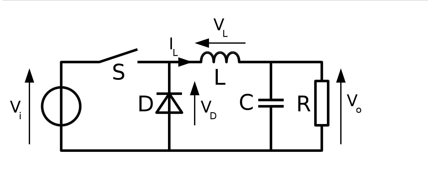
This is the most basic circuit diagram of buck converter(from Wikipedia). It consists of one dc source, one switch, one diode, one inductor and one capacitor. The resistor R here represents the load.
When the switch is closed, current flows through the inductor and charges the capacitor, and then goes back to the negative terminal of the dc source. (Diode is reverse biased so there is no current in the diode)
When the switch is open, the current inside the inductor continues to flow through the rest of the circuit (because of the characteristic of an inductor), and then goes through the diode this time.
The general idea of a buck converter is to:
first, convert a constant dc voltage into square wave by switches(or diodes);
second, change the duty cycle of the “square wave” to change the dc voltage level;
third, use the LC filter to smooth the “square wave” into a constant dc voltage, however this dc voltage might be different from the initial one because of the change of the duty cycle in second step.
When are reading power electronics materials, you will meet with the term “transfer function”. Transfer function is actually the ratio of ‘output’ and ‘input’. They are not necessarily output and input voltages or currents, they can be other things such as duty cycle. For buck converters, Vout/Vin = Duty Cycle.
Several things to notice:
- Duty cycle or duty ratio is a number from 0 to 1. It is not a percentage. We know that 10% is 0.1, but just from definition point of view, it is more “correct” to say 0.1 DC instead of 10% DC.
- The choice of values of inductors and capacitors is important to decide how smooth the output voltage will be. It is essential to make sure the cutoff frequency of LC filter to be well below the switching frequency. For definition: LC frequency = 1/(2*pi*sqrt(L*C)); and usually, we have “okay” output if switching frequency is over 10*LC frequency; and we have “good” output if switching frequency is over 50*LC frequency.
Synchronous Buck Converter
In real applications, most of the time the diode is replaced with another switch, which is called synchronous buck converter. In DC DC conversion, most switches are MOSFETs. Synchronous buck converter definitely increases the complexity of the design, and cost of components(diodes are cheaper than MOSFETs), but there are several benefits of this modification.
First, less loss. MOSFET has much lower loss than diode, so the converter efficiency can be improved. Ususally, the power loss is related to the duty cycle, and low duty cycle operation has higher losses.
Second, with this second switch, this topology can be also accessible as a ‘boost converter’, which can step up a dc voltage. I will probably cover the topic of boost converter in following articles.
To be continued……
reference:
https://en.wikipedia.org/wiki/Buck_converter
Yingzhang Dong
Austin, TX
2016
This article is originally written by Yingzhang Dong, and please note source if you would like to quote.